Page 41 - Fister jr., Iztok, and Andrej Brodnik (eds.). StuCoSReC. Proceedings of the 2018 5th Student Computer Science Research Conference. Koper: University of Primorska Press, 2018
P. 41
0.5 − arc sinh[tan(2M [V − 0.5])] . (8)
2π
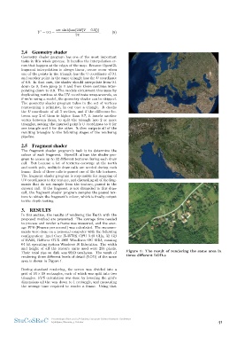
2.4 Geometry shader Figure 1: The result of rendering the same area in
three different LOD-s
Geometry shader program has one of the most important
tasks in this whole process. It handles the interpolation er-
rors that happen at the edges of the map. Because OpenGL
fragment interpolation is always linear, errors occur when
one of the points in the triangle has the U coordinate of 0.1
and another point in the same triangle has the U coordinate
of 0.9. In that case, the shader should interpolate from 0.1
down to 0, then jump to 1 and from there continue inter-
polating down to 0.9. The models circumvent this issue by
duplicating vertices at the UV coordinate wrap-arounds, so
if we’re using a model, the geometry shader can be skipped.
The geometry shader program takes in the set of vertices
representing a primitive, in our case a triangle. It checks
the U coordinate of all 3 vertices, and if the difference be-
tween any 2 of them is higher than 0.7, it inserts another
vertex between them, to split the triangle into 2 or more
triangles, setting the inserted point’s U coordinate to 0 for
one triangle and 1 for the other. It then outputs all of the
resulting triangles to the following stages of the rendering
pipeline.
2.5 Fragment shader
The fragment shader program’s task is to determine the
colour of each fragment. OpenGL allows the shader pro-
gram to access up to 32 different textures during each draw
call. But because a lot of textures converge at the north
and south pole, multiple draw calls are needed during each
frame. Each of those calls is passed one of the tile textures.
The fragment shader program is responsible for mapping of
UV coordinates to the texture, and discarding all of the frag-
ments that do not sample from the texture, passed in the
current call. If the fragment is not discarded in this draw
call, the fragment shader program samples the passed tex-
ture to obtain the fragment’s colour, which is finally output
to the depth testing.
3. RESULTS
In this section, the results of rendering the Earth with the
proposed method are presented. The average time needed
to process and render a frame was measured, and the aver-
age FPS (Frames per second) was calculated. The measure-
ments were done on a personal computer with the following
configuration: Intel Core i5-3570K CPU 3.40 GHz, 32 GB
of RAM, GeForce GTX 1060 Windforce OC 6GB, running
64 bit operating system Windows 10 Education. The width
and height of all the texture units used were 256 pixels.
Their total size on disk was 9560 terabytes. The result of
rendering three different levels of detail (LOD) of the same
area is shown in Figure 1.
During standard rendering, the screen was divided into a
grid of 10 × 10 rectangles, each of which was split into two
triangles. FPS calculation was done by lowering the grid’s
dimensions all the way down to 1 rectangle, and measuring
the average time required to render a frame. Using that
StuCoSReC Proceedings of the 2018 5th Student Computer Science Research Conference 41
Ljubljana, Slovenia, 9 October
2π
2.4 Geometry shader Figure 1: The result of rendering the same area in
three different LOD-s
Geometry shader program has one of the most important
tasks in this whole process. It handles the interpolation er-
rors that happen at the edges of the map. Because OpenGL
fragment interpolation is always linear, errors occur when
one of the points in the triangle has the U coordinate of 0.1
and another point in the same triangle has the U coordinate
of 0.9. In that case, the shader should interpolate from 0.1
down to 0, then jump to 1 and from there continue inter-
polating down to 0.9. The models circumvent this issue by
duplicating vertices at the UV coordinate wrap-arounds, so
if we’re using a model, the geometry shader can be skipped.
The geometry shader program takes in the set of vertices
representing a primitive, in our case a triangle. It checks
the U coordinate of all 3 vertices, and if the difference be-
tween any 2 of them is higher than 0.7, it inserts another
vertex between them, to split the triangle into 2 or more
triangles, setting the inserted point’s U coordinate to 0 for
one triangle and 1 for the other. It then outputs all of the
resulting triangles to the following stages of the rendering
pipeline.
2.5 Fragment shader
The fragment shader program’s task is to determine the
colour of each fragment. OpenGL allows the shader pro-
gram to access up to 32 different textures during each draw
call. But because a lot of textures converge at the north
and south pole, multiple draw calls are needed during each
frame. Each of those calls is passed one of the tile textures.
The fragment shader program is responsible for mapping of
UV coordinates to the texture, and discarding all of the frag-
ments that do not sample from the texture, passed in the
current call. If the fragment is not discarded in this draw
call, the fragment shader program samples the passed tex-
ture to obtain the fragment’s colour, which is finally output
to the depth testing.
3. RESULTS
In this section, the results of rendering the Earth with the
proposed method are presented. The average time needed
to process and render a frame was measured, and the aver-
age FPS (Frames per second) was calculated. The measure-
ments were done on a personal computer with the following
configuration: Intel Core i5-3570K CPU 3.40 GHz, 32 GB
of RAM, GeForce GTX 1060 Windforce OC 6GB, running
64 bit operating system Windows 10 Education. The width
and height of all the texture units used were 256 pixels.
Their total size on disk was 9560 terabytes. The result of
rendering three different levels of detail (LOD) of the same
area is shown in Figure 1.
During standard rendering, the screen was divided into a
grid of 10 × 10 rectangles, each of which was split into two
triangles. FPS calculation was done by lowering the grid’s
dimensions all the way down to 1 rectangle, and measuring
the average time required to render a frame. Using that
StuCoSReC Proceedings of the 2018 5th Student Computer Science Research Conference 41
Ljubljana, Slovenia, 9 October